Hydraulic fracture modeling is the process of predicting how a fracture will initiate, grow, and behave during a fracturing treatment. It combines fluid flow, rock mechanics, and fracture propagation to estimate key outputs such as fracture length, height, width, and proppant placement.
These models are essential for designing treatments, optimizing fluid and proppant volumes, and improving production performance.
Why Do We Need Modeling?
In the field, we cannot directly observe fractures at reservoir conditions. Modeling allows us to:
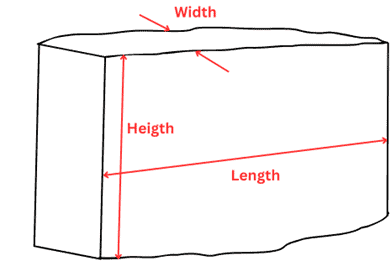
- Predict fracture geometry (length, width, height)
- Estimate fluid leakoff
- Evaluate proppant transport and placement
- Optimize treatment design
Types of Fracture Models
- PKN Model (Perkins–Kern–Nordgren)
The PKN model assumes a fracture with constant height, where growth occurs mainly in the length direction. The fracture width is controlled by the fracture height, and the cross-section is typically elliptical.
Fluid flow is described using a lubrication approximation, and fracture opening is governed by linear elasticity. The model assumes no vertical flow, meaning each vertical cross-section behaves independently.
This model is most appropriate for long, narrow fractures where the fracture length is much greater than its height. It is widely used because of its simplicity and ability to provide analytical solutions for fracture length, width, and pressure evolution.

- KGD Model (Khristianovic–Geertsma–de Klerk)
The KGD model assumes deformation in the horizontal plane, with fracture width varying along the fracture length. Unlike the PKN model, fracture width is controlled by the fracture length, not the height.
The model is based on plane strain conditions and includes coupling between fluid flow and rock deformation. It also assumes a constant fracture height but allows for a different pressure distribution compared to PKN.
The KGD model is more suitable for fractures where the height is large relative to the length, or when fracture geometry is more “radial-like” in the vertical plane.
- Radial Model
Radial models describe fractures that grow symmetrically in all directions from the wellbore, forming a circular (penny-shaped) geometry.
These models are used when there is no strong stress contrast to confine the fracture vertically, allowing it to expand equally in all directions. Fracture propagation is described in radial coordinates, and both elasticity and fluid flow are coupled.
Radial models are commonly applied in early-time injection or in formations where fracture containment is weak.
- Pseudo-Three-Dimensional (P3D) Models
P3D models extend 2D models by allowing the fracture height to vary along the fracture length. This removes the unrealistic assumption of constant height used in PKN and KGD models.
These models account for stress contrasts between layers, which control vertical fracture growth and containment. Fluid flow is still simplified, but vertical variations are included.
P3D models provide a better representation of real reservoirs, especially in layered formations, while remaining computationally manageable.
- Three-Dimensional (3D) Models
Fully 3D models simulate fracture growth in all spatial directions, without assuming constant height or simplified geometry. They couple:
- rock deformation (elasticity)
- fluid flow
- leakoff
- and often proppant transport
These models require numerical methods such as finite element or boundary integral techniques due to their complexity.
They are the most accurate but also the most computationally expensive, and are typically used for detailed fracture design and advanced simulations.