
Cracking under Pressure
As you are probably aware, rocks are hard. A given rock body has a certain tensile strength – a natural resistance to being pulled apart. In addition, deep underground, where hydraulic fracturing takes place, confining pressure squeezes rocks from all sides, making them even more difficult to fracture.
By increasing the pressure in the pores of a reservoir rock, we’re able to overcome the forces pushing inward on the rocks. When the pore pressure exceeds the combined forces of confining pressure and tensile strength, the rock will fracture
Hydraulic fracturing operations increase the pore pressure within a rock unit by pumping in large volumes of fracturing fluid. The faster the fluid is pumped in, the higher the pressure will become. Eventually, the pressure will be high enough to fracture the rock.
That explains how we’re able to fracture the rocks. But how are operators able to predict the direction the fractures will take? And how do they ensure that hydraulic fracturing won’t cause earthquakes or head off in the wrong direction?
The answer has to do with the local stress field.
Stress Regimes
In order to predict possible safety hazards that might accompany the drilling of a well, it is worth the effort to get a good understanding of stress regimes. Stress regimes describe the relative magnitudes of the pressures acting in different directions at any given spot in a rock. There are three stress directions in any material that are perpendicular to each other and they are called principal stresses.
The vertical direction is the most intuitive of the earth’s principal stresses. The layers of rock that are stacked above any given point push downward and squeeze that rock. When you squeeze the rock vertically like this, it wants to expand laterally, just like when you squeeze a sandwich between two pieces of bread, and all the fixings want to squirt out sideways.
However, underground, when rock tries to squeeze out laterally, it can’t because there is already other rock there. This rock pushes back in resistance through the horizontal stresses, keeping the rock relatively stable.
If the vertical stress is pushing harder, though, there will be some lateral movement, or what geologists call stretching.
The horizontal stress has a minimum and maximum value, depending on the direction. The strongest horizontal stress is called the maximum horizontal stress (or SHmax) and the other is called the minimum horizontal stress (or SHmin). They are always perpendicular to each other.
The strength of these two stresses compared to the vertical stress is how we determine which type of stress regime we’re under. The key thing to understand is that in any given stress state, there is a predominant shortening direction (parallel to the strongest compression) and there is a stretching (or extension) direction parallel to the least compressive stress.
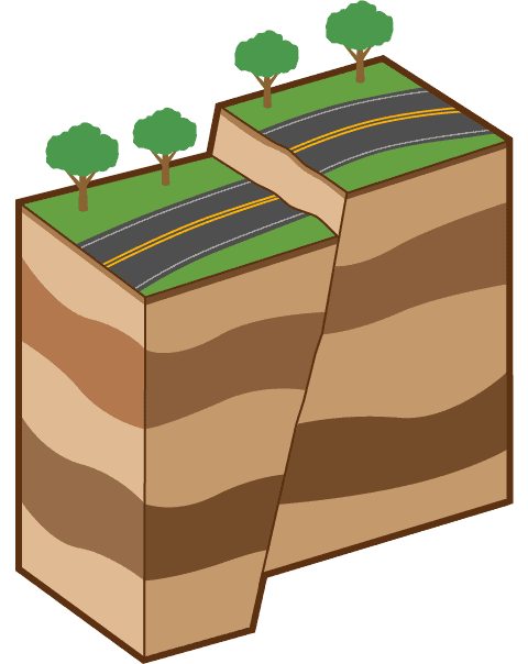
Normal Fault Regimes
If the vertical stress is the greatest, the earth’s crust will get thinner, but expand or extend against the least compressive stress, which in this case is the minimum horizontal stress, SHmin. The condition of having the vertical stress be the greatest is called a normal faulting stress regime, because normal faults are the primary geologic features that accommodate horizontal extension of the earth’s crust.
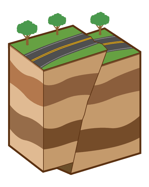
Thrust Fault Regimes
If the vertical stress is the least compressive stress, then the earth shortens horizontally, parallel to the most compressive stress, SHmax. This state is called a thrust faulting stress regime because the geologic feature that is associated with horizontal shortening is a thrust fault (a low-angle reverse fault, i.e. less than 30 degrees).
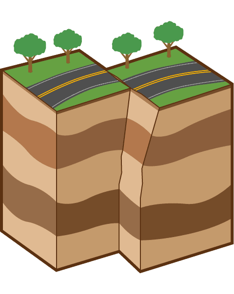
Strike-slip Fault Regimes
The third and final stress regime is in between the other two, with the vertical stress being less than the maximum horizontal stress but greater than the minimum horizontal stress. This is called the strike-slip faulting stress regime, where the shortening direction and fault movement direction is horizontal and parallel to SHmax.
If the relative magnitudes of the earth’s three principal stresses are known for a local area, particularly how big the horizontal stresses are relative to the vertical stress, better decisions can be made with regards to drilling and stimulating a well. Hydraulic fracturing issues and wellbore stability problems can be predicted, among other operational aspects.
The vertical stress is really easy to estimate based on the height of the rock column. The other two stresses are much more challenging to calculate, and for now we’ll leave that to the experts.
Fractures tend to form along a plane perpendicular to the direction of least principal stress. Remember, this is the direction in which it’s easiest to push rocks apart and fracture them – the path of least resistance.
Material Elastic Properties of Rocks
Engineers are able to determine how much pore pressure it will take to create fractures, and what the particular fracture orientation will be. But they also want to be able to predict how wide and long these fractures will be. To accomplish this goal, they measure two important material elastic properties of the formation rocks: Young’s Modulus and Poisson’s Ratio.
Both Young’s Modulus and Poisson’s Ratio describe elastic properties that dictate how a mass of rock will respond to changes in stress. In other words, they predict how much deformation the rock will experience based on how the stress is changed.
Young’s Modulus
Young’s modulus describes the “stiffness” of a rock. This becomes important during hydraulic fracturing operations.
A high Young’s modulus indicates that large stress is required to deform or strain a rock a given amount, while a low value means that less stress is needed to get the same amount of deformation.
Imagine a cylinder made of rubber. If you apply a stress to the cylinder along its vertical axis, it’s going to shorten along that axis.

The amount of stress applied divided by the shortening is Young’s modulus.
It is the same concept as a spring. A stiff spring acts like a material with a higher Young’s modulus than a flexible spring.


In terms of fracturing rock, Young’s modulus tells us how long and how wide our fractures might be. When fracturing fluid is pumped into rock, it causes changes in the stress state resulting in deformation.
The deformation increases with these changes and with increasing stress until the strength of the rock is reached, at which point the rock will fracture. The width of a fracture is closely related to the amount of expansion the rock undergoes before it breaks.
Knowing how wide and how long the fractures might be is important because it helps us predict the necessary fracturing fluid volume and the volume of oil and gas that we could theoretically produce out of these reservoirs. It also allows us to select appropriate proppants to keep the fractures open until the fracturing pressure is removed.
The second important elastic parameter is Poisson’s Ratio.
Poisson’s Ratio
Poisson’s Ratio describes how much a material will expand in one plane when compressed in a direction perpendicular to that plane.

Remember when we applied a stress to our cylinder of rubber in one direction? Roughly speaking, as the rubber deforms, the volume must remain constant.
While it is shortening in the direction of the applied stress, it must expand laterally to maintain its volume, as seen in this series of illustrations:


If we measure the ratio of the lateral expansion (how much wider it gets) to the stress-parallel shortening (how much shorter it gets, vertically), then we can quantify Poisson’s ratio.
Normal geo-materials have Poisson’s ratios ranging from 0 to 0.5. Highly incompressible materials like rubber and clay, which maintain a nearly constant volume when compressed, have Poisson’s ratios approaching 0.5. The three cylinders above (when viewed as a sequence) represent a substance with a higher Poisson’s ratio.
Materials that don’t expand laterally in response to compression, like foam and cork, have a ratio close to zero. Putting vertical stress on a rock with a Poisson’s ratio of zero would result in a compression that looks like this:


A Poisson’s ratio of less than zero would mean an object would contract laterally when squeezed vertically. That’s not something we see in nature very often, but substances and matrixes that act like that do exist in the lab and are interesting for scientists working in many fields. We aren’t going to talk about them more here, but it helps to understand the math to see how they work. A substance with a Poisson’s ratio of less than zero (approaching – 0.5) would look something like this when compressed in the vertical direction:


Porous rocks like sandstone and carbonate have Poisson’s Ratios ranging from 0.1 to 0.3. This contrasts with shales and coal beds, which have ratios closer to 0.5.
So what do Young’s Modulus and Poisson’s ratio have to do with drilling or fracturing?
As gravity compresses a formation rock from above, the rock tries to expand laterally to the degree predicted by Poisson’s ratio.
However, in typical subsurface conditions, rock is unable to expand because it is contained on all sides by more rock. The result is that a horizontal compression occurs within the formation. Once operators know the component of stress contributed by Poisson’s Ratio, they can perform pumping tests to determine any additional stresses acting horizontally on the rock column.
If they know what kinds of rocks they are dealing with, Poisson’s ratio allows them to predict horizontal stresses all along the borehole.
The reason operators want to do this is because it will inform them whether they need to be concerned about borehole compression, lost circulation, stuck pipe, pipe shearing, or deformation of pipe, among other things.
Holding the Fractures Open
When a fracture forms, the forces pushing the rocks together haven’t gone away – they’re just being counteracted by the pumping pressure exerted by the pressure pumping trucks. If the water pressure was reduced, the fracture would snap shut again, closing off a potential hydrocarbon flow path.
Operators don’t want that to happen. To prevent fractures from closing, they use proppants.
Proppants are granular materials that are forced into the fractures created by hydraulic fracturing fluids during pumping and ‘prop’ the induced fractures open. Once the proppants are in place, the pressure applied by the pressure pumping trucks can be removed – the proppants will maintain the fractures. Proppants act like sand between the pages of a book. The pages can never fit snugly together again as long as there are grains of sand between them.
Proppants need to be strong enough to resist the pressure of the surrounding rocks, but shaped in a way that allows gas and oil to pass between them. Typically, the cracks formed during hydraulic fracturing are wider than a single proppant grain. The crack is held open by a mass of proppant grains all pressed against each other.
That’s hydraulic fracturing in a nutshell: Pressurized fluids are pumped into formation rocks, causing them to fracture in a predictable way. As the fractures open, they are held apart with proppant materials. The fluid pressure is then reduced and production begins.
Let’s go into the details of planning and executing a hydraulic fracturing job in the real world.
Images: “Fracking Render” by Top Energy Training