

Apologies! Due to the interactivity required for this course component, we're afraid that your browser is incompatible. If you need assistance, please review our Technical Requirements
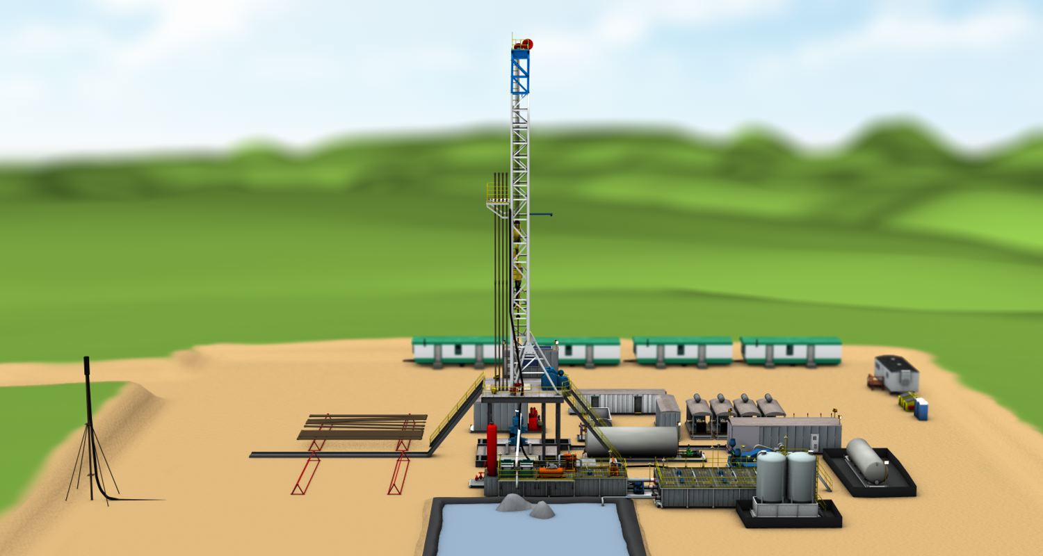

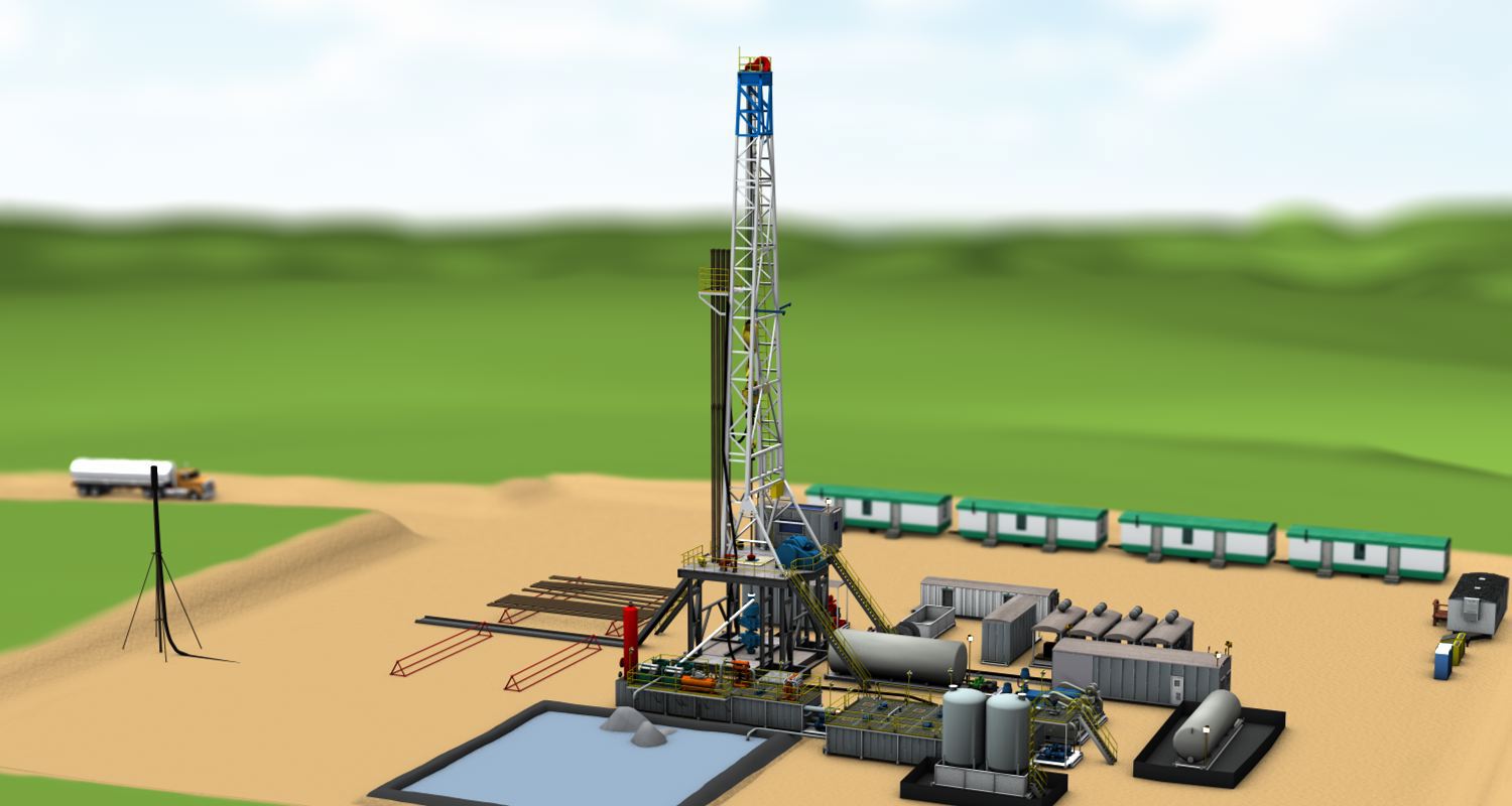
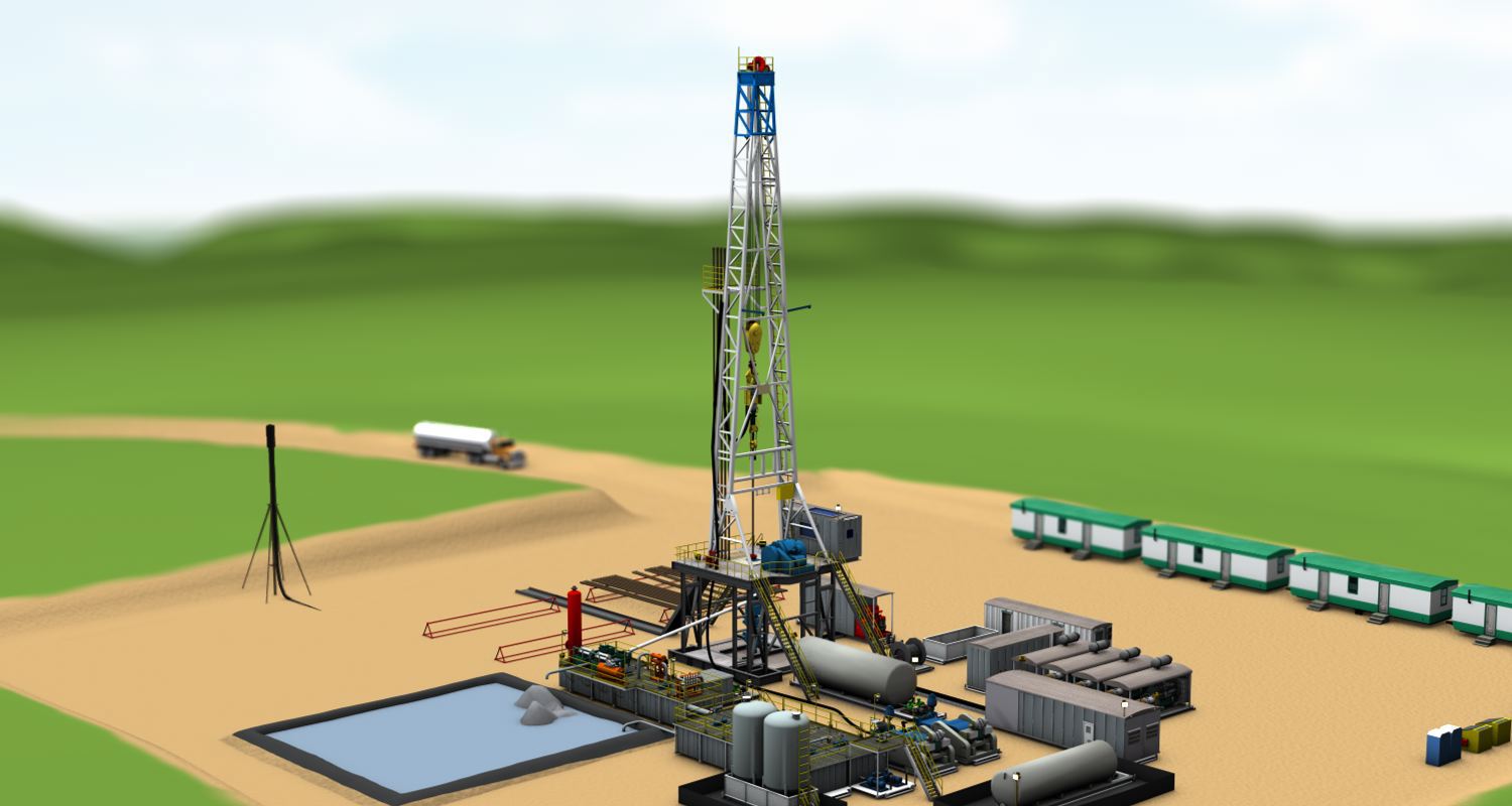
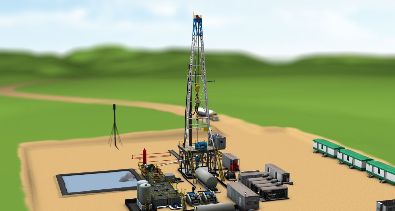
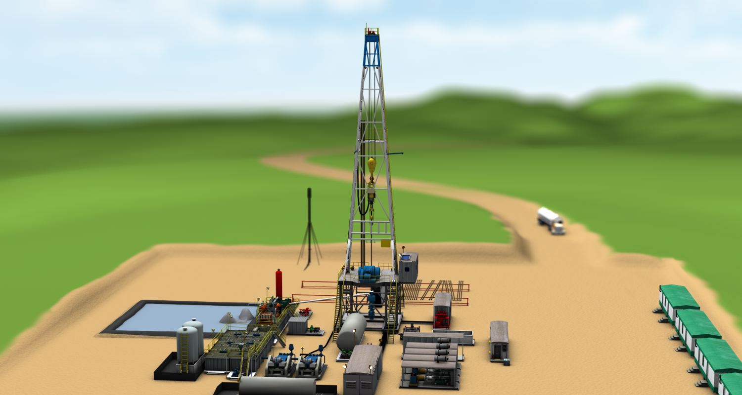
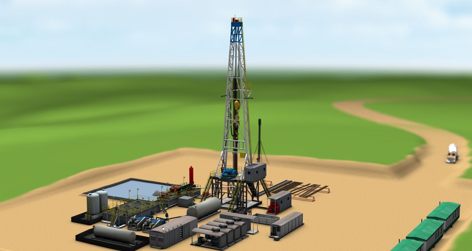
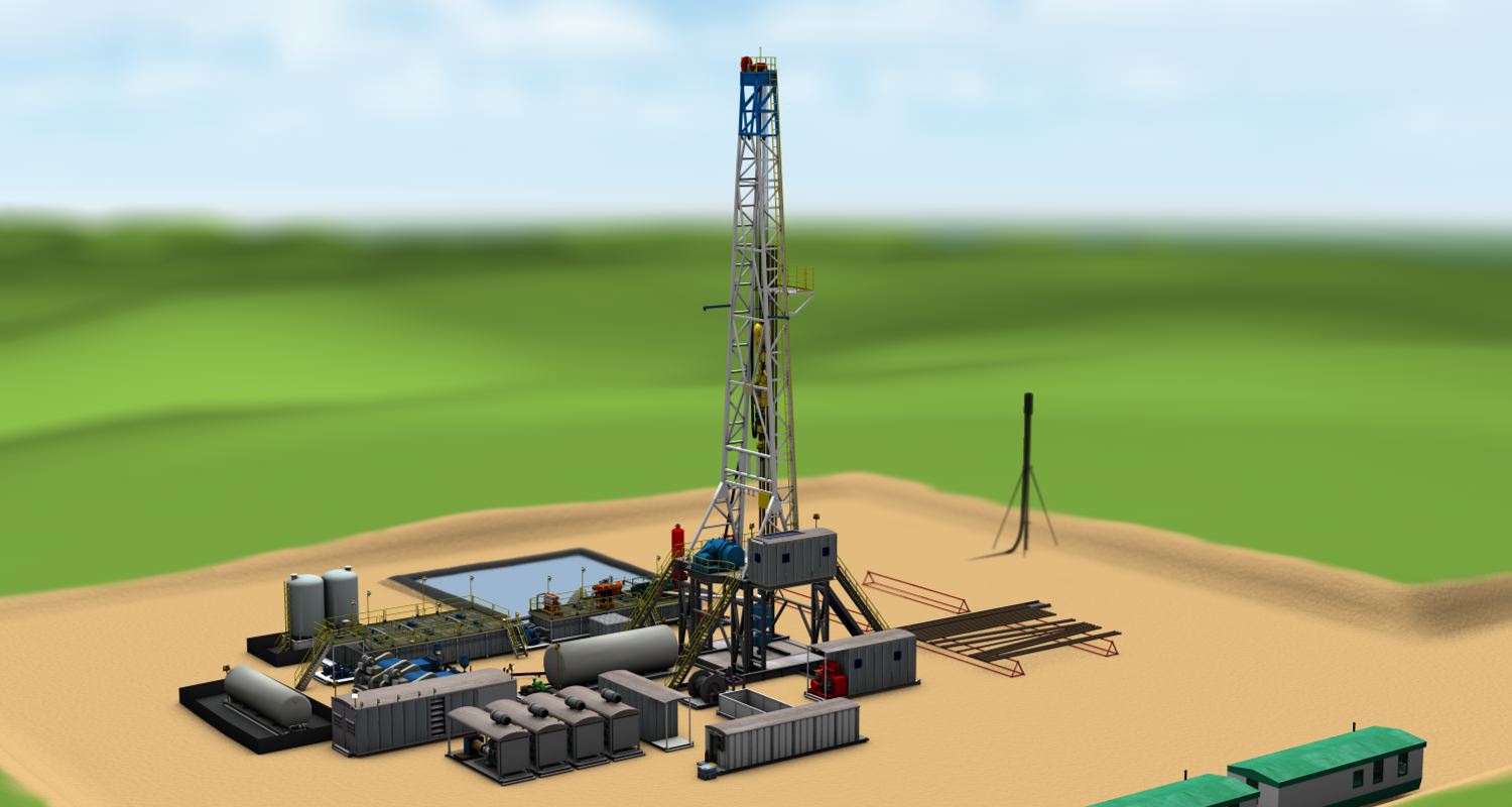
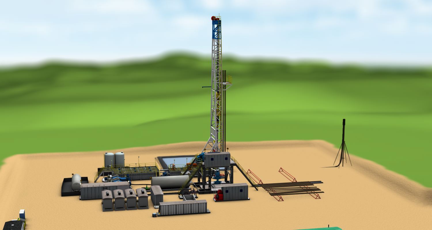
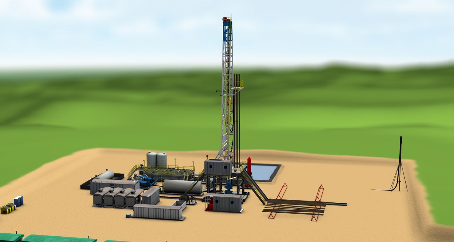
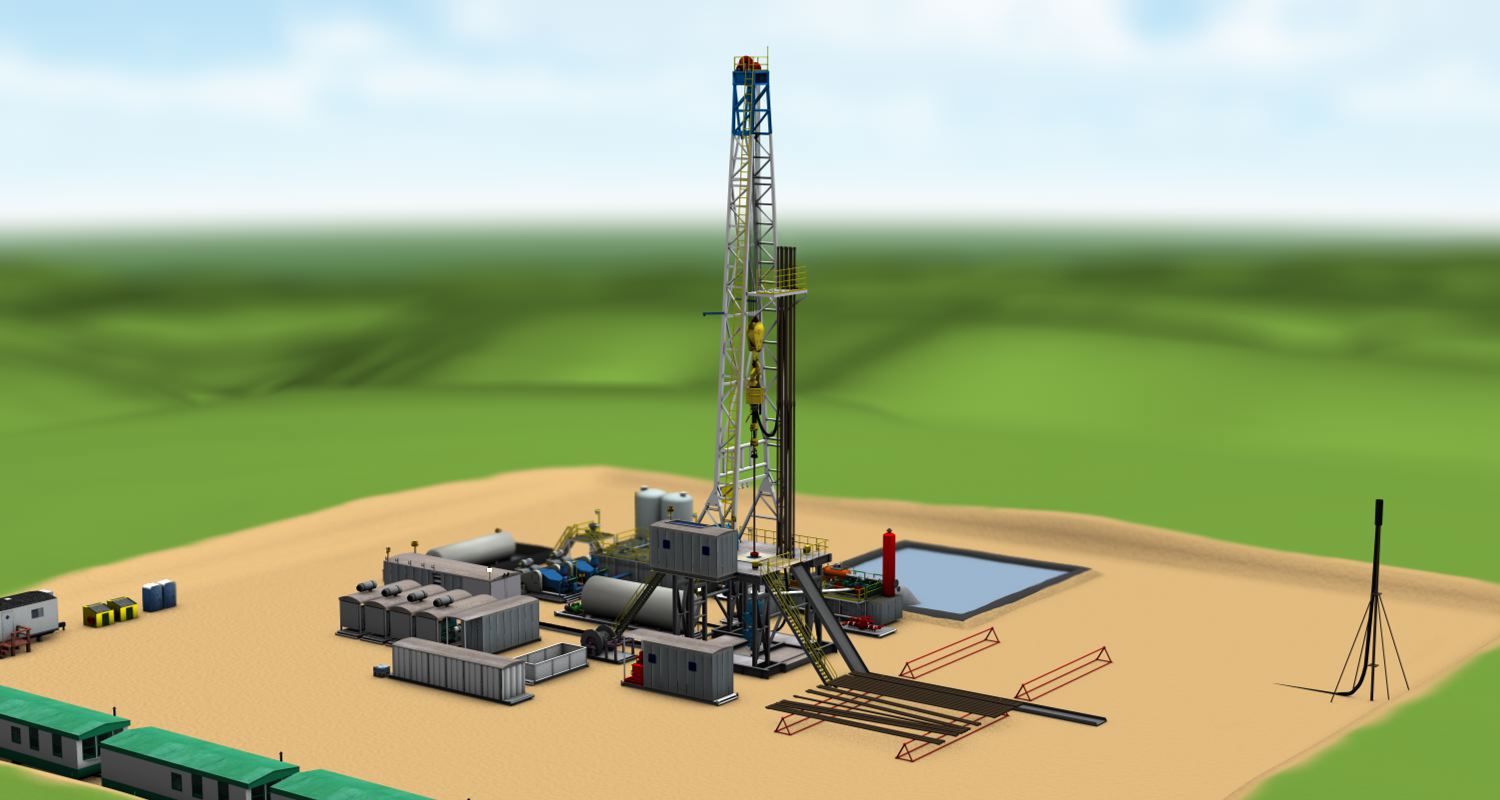
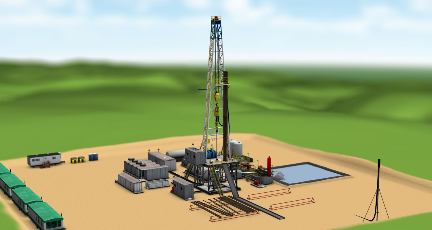
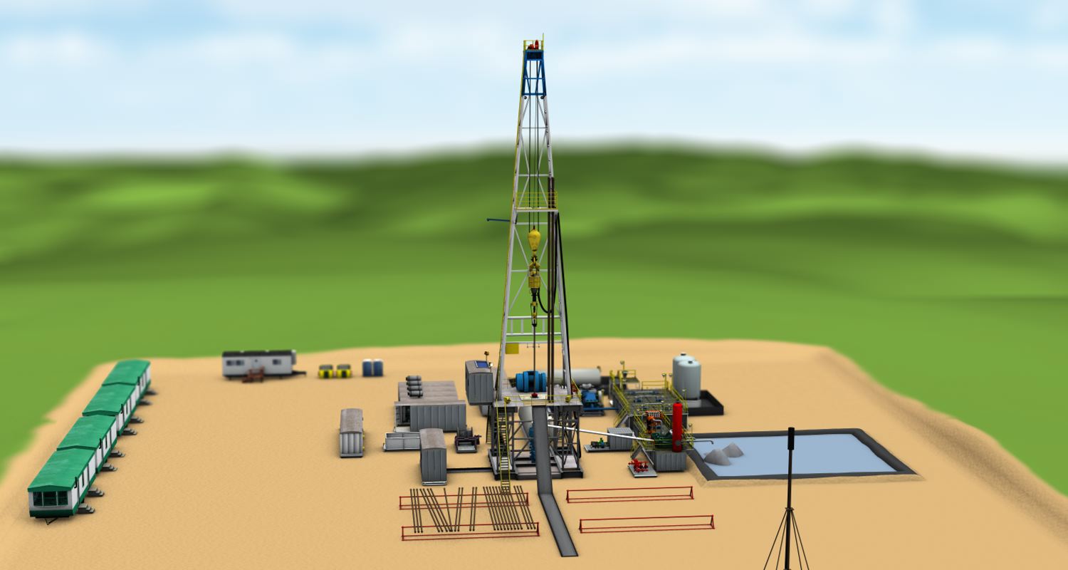
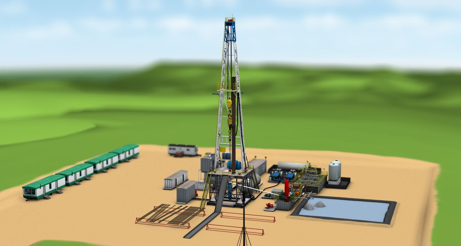
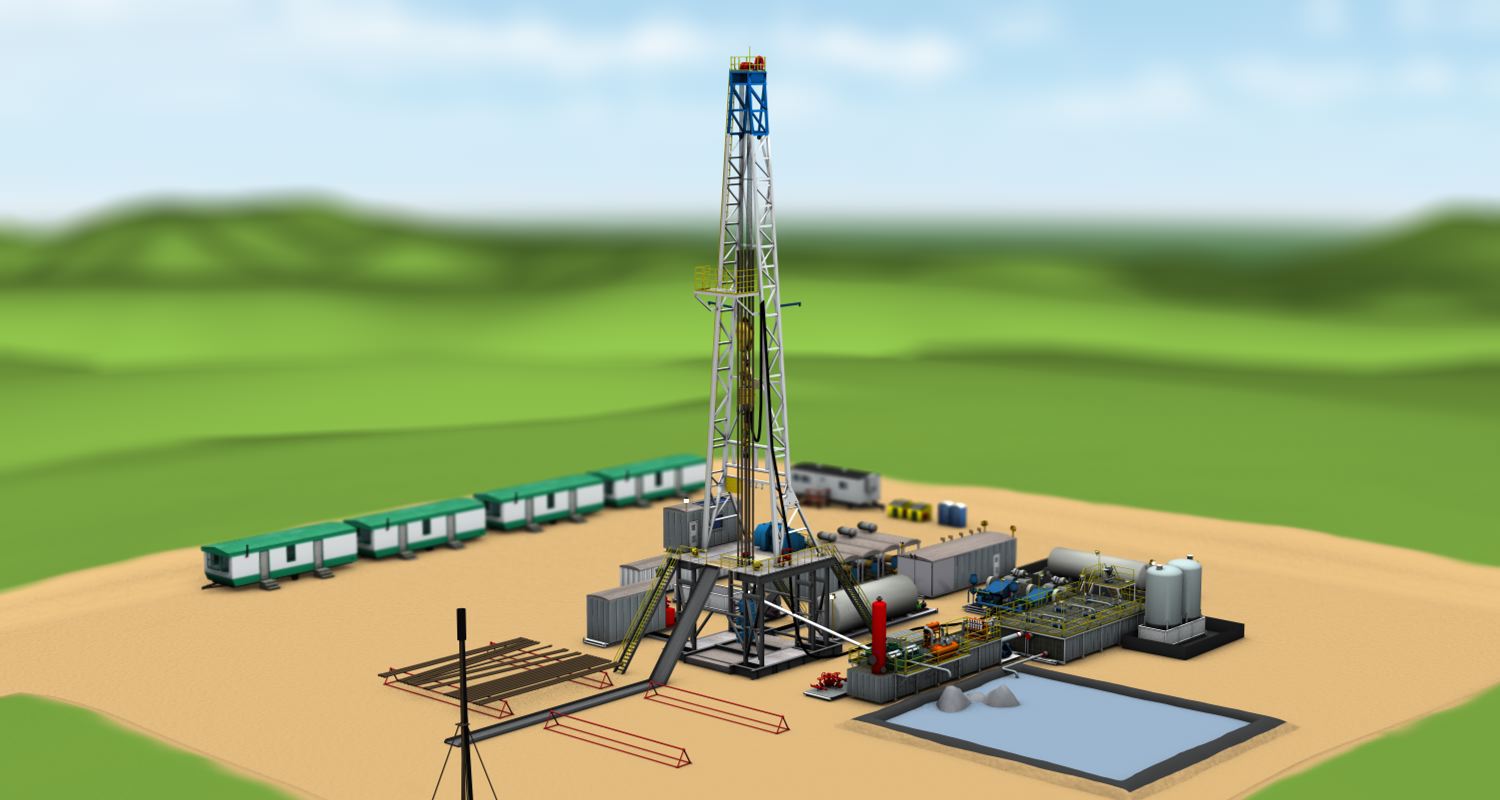
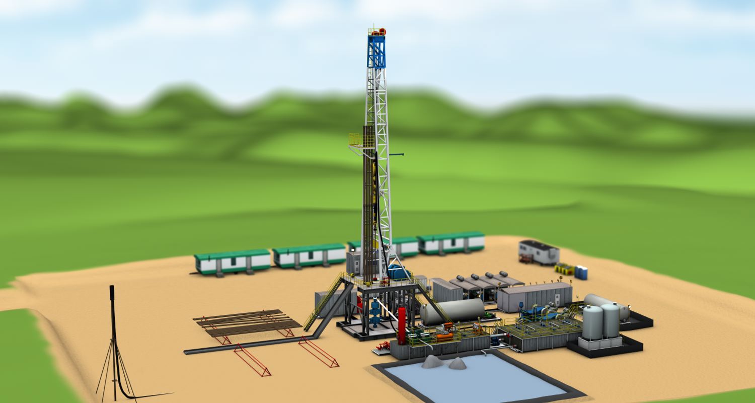
Explore this interactive drilling rig and pad with Paul Bommer, Senior Lecturer, Department of Petroleum and Geosystems Engineering, The University of Texas at Austin.
Rotate the drill pad with the slider in the upper right, click on the numbered dots, or alternatively, select a specific component from the list below and it will be opened for you.
The earliest rigs ran on steam engines, which were connected to a mechanical system that provided power to the important parts of the rig. By the mid 20th century, steam had been replaced by diesel, which is more efficient and reliable. In a mechanical diesel power system, a series of chains and clutches transmit power to the pumping, rotating, and hoisting systems.
Most modern rigs are what we call diesel-electric. These rigs still rely on diesel engines for power, but the engines are used to generate electricity, which is then transmitted to the rig systems, which have individual electric motors.
Diesel electric systems have several advantages over their mechanical counterparts. First, they can be placed further away from the rig. This provides quieter working conditions and reduces the danger of a fire caused by the ignition of fumes on the rig. Secondly, they are easier to install and maintain. Rather than aligning a complex series of mechanical parts near the rig, workers need only to run power cables to where they are needed.
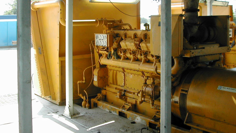
Engines provide mechanical power to the generators.
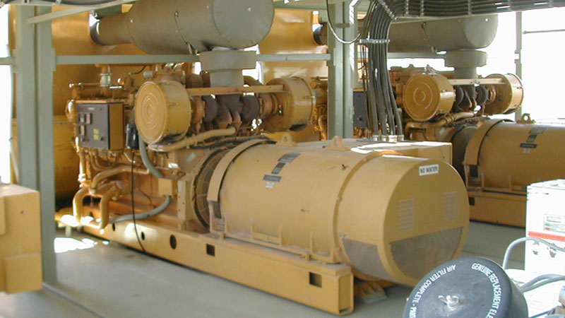
Generators convert the mechanical energy generated by the diesel engines into alternating current electricity.
These tanks typically contain diesel, which is used to power the generators and other rig equipment. Fuel tanks are usually made of metal or fiberglass.
A mud gun is a nozzle that prevents mud from settling out in a mud tank. Typically, mud is pumped from the tank, passes through a length of pipe, and is sprayed back into the tank at high pressure beneath the mud surface. This keeps the mud moving in the tank so it won’t settle. Bottom type and non-spinning type mud guns protrude from the bottom of the tank (non-spinning types have an adjustable aim). Spinner / pivot mud guns rotate at a high rate, spraying mud across the entire tank (the rotation is powered by the mud itself).
The monkey board is a platform about halfway up the derrick. The board is essentially a rack that is used to secure the upper end of a stand of pipe when it is removed from the well. The worker who guides pipes into the board is called the derrickman.
SCR is short for Silicon Controlled Rectifier. An SCR is essentially a continuously variable high voltage switch with no moving parts that can be controlled with a smaller electric current. The SCR house contains the equipment that controls the electricity traveling to the different rig systems
The mud mixer is where drilling mud is made from bentonite clay and water. Barite and other materials are added to increase the density of the mud.
The floor of the drill rig, where most drilling operations occur. Typically contains a rotary table, control systems, tongs, and other operational equipment. Is elevated above the ground by the substructure.
The mud tank (or mud pit, depending on site setup) is the place where drilling mud is stored until it is needed. Used drilling mud flows into the mud tank after it has passed through the shale shakers and mud cleaners. Mud is withdrawn from the tanks through the suction line of the mud pumps.
A cable tray is a heavy-duty, rack-like tray that is used to conduct large wires safely across the drill site.
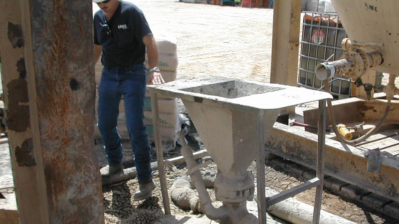
The hopper where liquids and powders are mixed together to make mud. The liquids enter through a pipe. The solids are added into a hopper, where they are mixed with the water and flow out through a line to the mud tank.
The crown block is a fixed system of pulleys at the very top of the rig.
A hollow length of pipe composed of many segments screwed together, the drill string transmits rotational energy and drilling fluids to the drill bit at the bottom of the well. The drill string diameter will decrease after each section of casing is cemented.
Mud mixing pumps move the liquid component of the mud into the mud mixing hoppers, where powdered components are added.
Pulsation dampeners serve to reduce pressure fluctuations in the mud line. These fluctuations, caused by the mud pumps, can render sensors inaccurate, damage pipes and reduce operational efficiencies. The dampener is a chamber attached to the mud flow line containing a nitrogen-filled bladder. The bladder absorbs the pressure pulsations because the gas within is compressible.
The control panel and instrument readout center of the drill rig. From here, the driller controls all operations of the drilling rig. Instrument readouts include hoisting weights, mud pressures, and other indicators that allow the driller to keep track of all the rig systems. By monitoring the console readouts, the driller plays a major role in ensuring the safety of the rig.
The mud pumps suck up mud from the mud tank and pump it through the drilling system. They are typically at least two mud pumps on a drill site.
The bell nipple is a large diameter section of pipe found just above the blowout preventer. The drill string passes through it and into a smaller pipe up above. Fluids flowing in the annulus are captured in the bell nipple and exit through the flow line, which attaches to the bell nipple horizontally on one side.
The flow line carries fluid from the bell nipple to the mud tanks or mud pit.
Connects the mud pumps to the standpipe. Designed to withstand high vibration and pressure pulsations.
The swivel allows the kelly to rotate while suspended from the travelling block. Importantly, it allows drilling fluid to flow from the stationary standpipe to the rotating drill string.
The tongs are essentially large hydraulic pipe wrenches that can grip pipe joints when making up (screwing together) and breaking out (unscrewing) drilling pipe. After the floorhand tightens the tongs on the pipe, a cat-head built into the draw works pulls on a cable, turning the tongs and tightening (or loosening) the pipe. The tongs are pushed back into neutral position by workers.
The draw-works consists of a powerful electric motor attached to several spools which can be used to wind and unwind cables. The main spool holds the drilling line which is used to raise and lower the drilling assembly. Two smaller spools, called catheads, are used to pull on cables which move the tongs. Each spool can be engaged separately by the same motor.
An area where mechanical rig components are repaired. In a region with many rigs, a centralized workshop may be used to reduce costs.
A rack next to the bottom of the pipe ramp where drilling pipe and casing is stored until it is needed.
An indoor shelter containing coffee, personal storage space, meeting rooms, communications equipment, etc. It is typically installed to be level with the rig floor.
A gas flare allows rigs to burn off excess gas that cannot be safely or economically stored and transported. Gas is burned at the top of a flare stack containing a flashback prevention system to reduce the risk of uncontrolled burning. Flare stacks are typically located away from the rig to reduce fire hazards. In recent years flaring has been on the decline due to economic and environmental considerations.
The derrick is the tall structure that most people think of when they picture oil and gas drilling. It has two purposes:
First, it supports the weight of the drillstring and associated equipment, which can weigh more than two million pounds.
Second, it allows pipes to be hoisted completely out of the well in sections of up to around 100 feet.
A hole drilled in the ground beneath the rig floor. It is lined with pipe, including an extension that brings it up to the rig floor. The mousehole holds lengths of drilling pipe in preparation for adding them to the drill string.
A 30-35 foot deep cased hole beneath the rig floor where the kelly is stored during hoisting operations. Only present on kelly drive rigs.
A structural support on the mast that allows loads to be hoisted up the outside of the mast.
Also known as accumulator BOP control system. This is the system that provides the pneumatic pressure required to close the blowout preventer. The accumulator consists of a system for storing up pneumatic energy, which can be generated by an onboard motor or external rig systems. Energy is stored using compressed gas or another form of potential energy. This ensures that pressure will be available to activate the blowout preventer in the event of failure of rig power systems.
This blowout preventer consists of rubber “wedges” that can be extruded into the wellbore by hydraulic pistons. These wedges can create a powerful seal around drill-string pipes as well as irregularly shaped pipes like kellys. Importantly, the pipe can be moved up and down while the preventer is engaged. Annular BOPs are not as effective at closing an open hole as the other types of BOPs.
The pipe ram BOP has two metal rams designed to close around the outside of a pipe of a certain size, preventing flow within the annulus while maintaining the integrity of the pipe and allowing flow within it. Variable bore pipe rams are designed to close around a variety of pipe sizes.
These BOPs consist of two rams that press together and seal off an empty borehole. They are unable to seal boreholes containing pipe.
Shear ram BOPs are the most effective, but also the most destructive. They sever the drill string and seal off the entire wellbore regardless of its contents.
A vertical track along which the top drive assembly slides. This holds the top drive and prevents it from rotating when turning the drill bit.
A hardened metal tool, typically made from tungsten carbide, used to drill through rock formations at the bottom of a well. Jets in the drill bit spray drilling mud at high pressure to clean the drill bit and remove cuttings and loose rock from the bottom of the hole. The two most common types of drill bits are roller cone bits, which have three cones that roll along rocks at the bottom of the bore and crush them, and polycrystalline diamond compact bits, which have no moving parts and scrape the bottom of the hole with industrial grade diamonds.
Thick walled steel piping used to connect the drill bit to the rotation source at the surface. Drilling mud is conducted downward inside the pipe and upward on the outside. Typically, the pipe comes in 30-33 foot sections. It is referred to by its weight per foot.
A high pressure, flexible pipe with an interior diameter of 3-5 inches that carries drilling mud from the standpipe to the kelly or topdrive. The pipe is longer than the distance between these parts in order to accommodate the up-down movement of the kelly or topdrive.
The trip tank is a separate mud storage tank that is used during tripping operations. Fluid from the trip tank is continually circulated through the well during tripping. Pumps associated with the tank ensure that the total height of the mud column in the hole remains constant during tripping operations. This is important for preventing blowouts.
A short length of hollow pipe used to connect the top drive to the drill string.
An elevator that brings personnel from the ground to the rig floor.
A large columnar tank used to separate gas from the drilling mud in the event of formation fluid intrusion into the well. The mud flows down a series of baffles. As gas bubbles out of the mud on the baffle, it rises along the underside of the sloped baffle above. At the top of each baffle, the gas is collected and typically sent through a line to a gas flare. The mud gas separator is placed just before the shale shaker in the mud flow path.
Instead of rotating the drill string with a kelly and rotary table, top drive systems use an electrically powered drive shaft that screws directly into the top of the drill string (kind of like an electric screwdriver or drill). As drilling progresses, the top drive system is lowered deeper into the hole.
The travelling block is part of the block and tackle system used to raise and lower the drill string. It consists of several pulleys in sequence, and it is raised and lowered along with the drill string.
The lines through which the mud flows from the mud pumps to the standpipe.
A small, usually prefabricated, lab where mud samples are analysed during drilling. This allows the mud engineer to ensure that the mud remains within the design specifications of the well.
A pipe carrying mud that surfaces around the annulus from the bell nipple to the mud tanks or mud gas separators.
A system for providing rotation to a drill string. A non-circular pipe known as a kelly is rotated by an adapter called a kelly bushing, which is in turn rotated by the master bushing and rotary table. The square or hexagonal cross section of the pipe allows it to be rotated while sliding up and down. This allows powered rotation and drilling to occur simultaneously.
The powered mechanism that provides rotational force to the kelly. It is a round table set into the floor of the rig containing a master bushing, which in turn contains the kelly bushing.
The master bushing sits right inside the rotary table. It often contains a bowl shaped depression that allows drillers to insert wedges, which hold up the drill string while it is unscrewed from the kelly. It is also designed to engage the kelly bushing, which is placed inside.
The kelly bushing is essentially an adapter that fits inside the master bushing and transmits rotation to the kelly, which will likely vary in size as drilling progresses and the diameter of the hole decreases.
A rectangular or hexagonal pipe that is screwed into the top of the drill string and transmits the rotation of the rotary table and kelly bushing to the string.
The drill line is a steel cable that supports the weight of equipment that is raised and lowered into the hole. The required strength of the drill line depends on the expected maximum load on the rig.
The suction line carries mud from the mud pit or tank into the mud pumps.
After mud passes through the mud pumps, it flows up the stand-pipe. The standpipe connects to the kelly or the top drive through a rotary hose.
A large hook attached to the travelling block by a suspension system. This is what drillers actually hang the topdrive or kelly from.
In a kelly drive system, the swivel allows drilling fluid to pass from the static standpipe into the rotating kelly. In a topdrive system, it does essentially the same thing at the top of the drill string.
The stairway allows workers to ascend from ground level to the rig floor. The pipe ramp provides a sloped surface along which drill pipe and casing can be pulled during hoisting operations. This allows pipes to be raised to the rig floor from the pipe rack safely.
A piece of equipment designed to control the release fluids from a well by reducing the pressure. The choke manifold allows for continued circulation of drilling mud after a BOP has been sealed. This is important because it allows drillers to circulate heavier mud and regain control of the well.
The shale shakers are used to remove rock cuttings that have come up from the bottom of the well from the mud so that it can be reused. The shale shakers consist of a vibrating grate. Rock chips are trapped in the grate and slide off of it, while mud flows between the metal parts.
The mast is the reinforced steel tower that supports drilling loads and allows hoisting through a system of pulleys.
A high pressure, flexible pipe with an interior diameter of 3-5 inches that carries drilling mud from the standpipe to the kelly or topdrive. The pipe is longer than the distance between these parts in order to accommodate the up-down movement of the kelly or topdrive.
A length of drill pipe that is raised and lowered from the hole. A stand typically consists of 1-3 pipe segments attached together. Stand length depends on the size of the rig. Longer stands allow drillers to work faster because they don’t require as many pipes to be “broken out” (unscrewed) and “made up” (screwed together).
The substructure supports the entire load of the drilling rig. Depending on surface conditions, it may be installed directly on the ground or it may be installed on a custom made foundation. Substructures are rated by maximum load and height (certain blowout preventer stacks may not fit under some substructures). Substructures for onshore drilling are designed to be easily moved, set up, and taken down.
The mud cleaning system removes any solid materials that may still be present in the mud after it passes through the shale shaker.
Also known as a hydrocyclone, this piece of equipment is located after the mud gas separator but before the desilting equipment. It operates on the concept of centrifugal force, which separates the denser impurities from the mud. Typically, this is found as part of an integrated “mud cleaner” system, which may contain many hydrocyclones.
A mud agitator is essential a motor attached to a propeller blade. The propellers are lowered into the mud tank and used to ensure continuous mud circulation within the tank, which prevents settling.
This is where mud additives are stored. The main goal is to keep the sacks dry and accessible.
The wellhead is the primary pressure containment system for a well. It is where surface equipment interfaces with the borehole. Typically, the well head is welded to the first string of casing cemented into the hole; drilling continues through the top of the wellhead and BOP, which is mounted on the wellhead.
The pipe rack is used to store drilling and casing pipe segments before they are hoisted onto the rig.
A platform at the very top of a rig mast that supports the crown blocks.